Secondary Port of a SAS Drive
Introduction
I was curious about a SAS drive that has a secondary port which is basically comprised of a pair of differential signals, TX/RX. However my HBA and backplane were not compliant with these redundant server drives so I decided to devise a patch.
The Drive
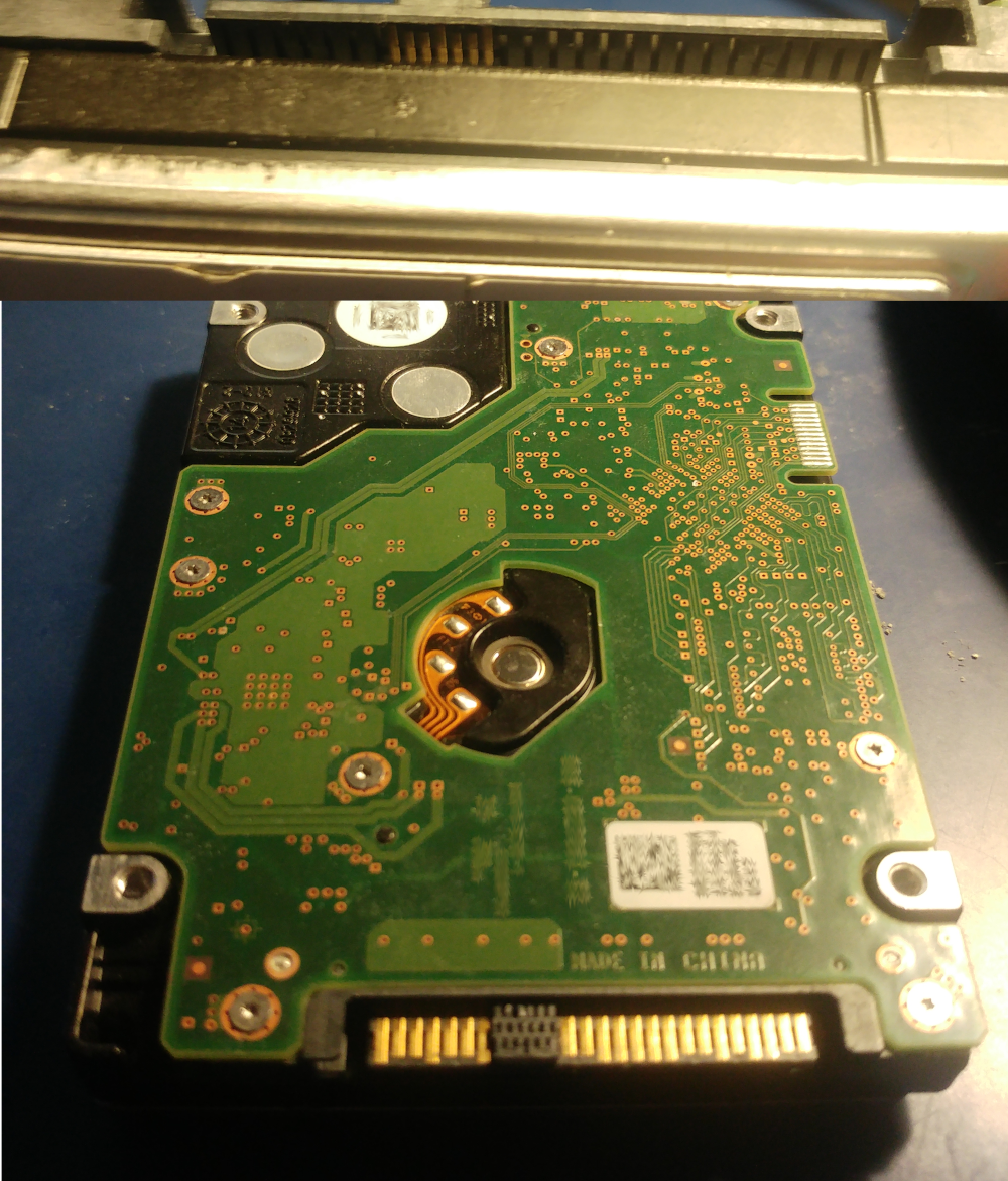
This is the Hitachi drive that I’ve been working on. It is an 2.5" 10k RPM with dual ports, pretty cool huh? If you have noticed, there is a second SAS port that can be observed at the top. However, the pins are on the other side of the board.
SAS Connector
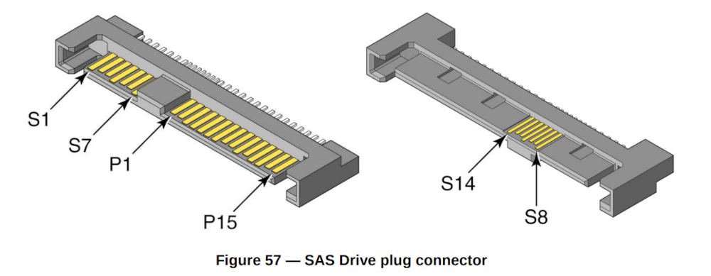
T10 names the differentials with symbol S as in T10/1601-D. The signals are as follows:
| Pin | Description |
|---|---|
| S1 | GND |
| S2 | RP+ |
| S3 | RP- |
| S4 | GND |
| S5 | TP- |
| S6 | TP+ |
| S7 | GND |
| S8 | GND |
| S9 | RS+ |
| S10 | RS- |
| S11 | GND |
| S12 | TS- |
| S13 | TS+ |
| S14 | GND |
P is for primary, S for secondary so RP+ becomes the positive receive (RX) line for primary port. Recall, differential pairs have positive and negative lines where the transmitted signal is the difference of those two. This reduces the effect of the noise in the signal when compared to parallel buses like IDE. TX’s are driven by two op-amps usually but we do not see them in the image.
The Problem
There is nothing wrong with the drive. I just wanted to see if the secondary SAS port is working and if there are any extra SCSI opcodes available through it. I already know the answer and it is false for the latter. A friend told me that the reason for the second port is just redundancy for high-availability storage systems. Never that rich I am afraid. Nevertheless, if you like to ship me a rack of expa(e)nsive storage system, feel free ;)
Ingredients
So I decided to start with a Fujitsu backplane. Don’t ask me how I acquired it, I tend to collect junk and my friends make phun of me all time but it’s OK. These parts come at handy from time to time just like this one.
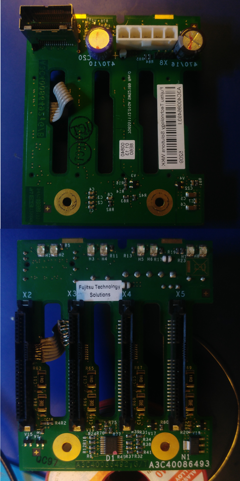
I’ve flipped the top view horizontally so don’t get confused.
The Patch
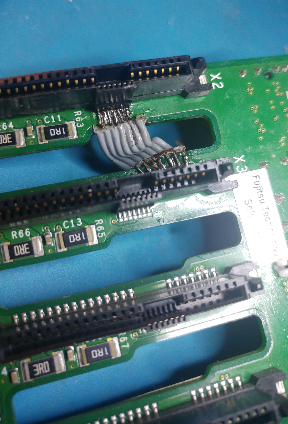
The idea is pretty simple, connect the secondary SAS port of the first connector to the primary port of the next connector. I’ve used ribbon cable and the following image depicts a bundle of seven. I admit my soldering skills are beyond indecent, at least SAS connectors are still left intact :p
Powering the backplane is the next problem to solve. It has a 1x5 Molex connector.
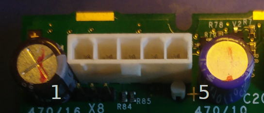
Pins are as follows:
| Pin | Description |
|---|---|
| 1 | +12V |
| 2 | GND |
| 3 | GND |
| 4 | +5V |
| 5 | +5V |
You can reverse the pinout by applying continuity test to Molex pins and the power pins of the any SAS connector on the backplane. A SAS power connector has +12V, +5V, +3V, GND. You might noticed +3V is not used. In fact, never seen a drive that requires +3V so far.
The other side of the connector is plugged into a HP DL360 Gen VO where VO stands for Veeery Old :p
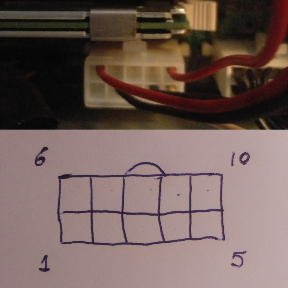
The connector is a 2x5 Molex type. You can measure the voltages while the server is running via a multimeter. The pinouts are as follows:
| Pin | Description |
|---|---|
| 1 | +12V |
| 2 | GND |
| 3 | +3.3V |
| 4 | GND |
| 5 | +12V |
| 6 | +5V |
| 7 | GND |
| 8 | +3.3V |
| 9 | GND |
| 10 | +5V |
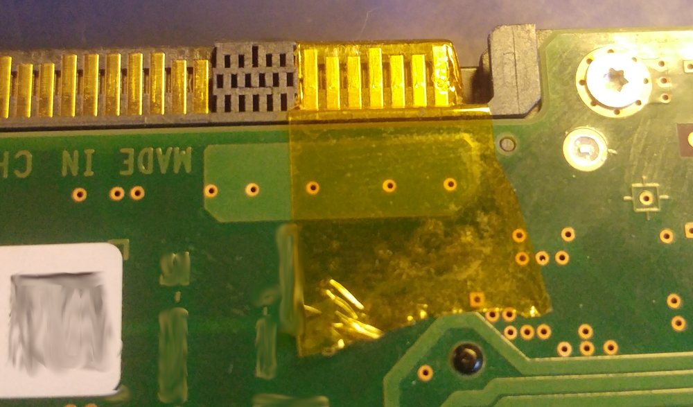
Finally, I’ve disabled the primary port of the drive via an engineering miracle called Kapton Tape :p
Results
I’ve used sg3_utils to gather information about the SCSI drive. Log Page 24 (0x18) tells us about the PHY’s.
# sg_logs /dev/sg3

... skipped for brevity ...

Protocol Specific port page for SAS SSP  (sas-2) [0x18]
relative target port id = 1
  generation code = 1
  number of phys = 1
  phy identifier = 0
    attached SAS device type: no device attached
    attached reason: unknown
    reason: power on
    negotiated logical link rate: phy enabled; unknown rate
    attached initiator port: ssp=0 stp=0 smp=0
    attached target port: ssp=0 stp=0 smp=0
    SAS address = 0x5000cca0436d646d
    attached SAS address = 0x0
    attached phy identifier = 0
    Invalid DWORD count = 0
    Running disparity error count = 0
    Loss of DWORD synchronization count = 0
    Phy reset problem count = 0
    Phy event descriptors:
     Invalid word count: 0
     Running disparity error count: 0
     Loss of dword synchronization count: 0
     Phy reset problem count: 0
relative target port id = 2
  generation code = 1
  number of phys = 1
  phy identifier = 1
    attached SAS device type: SAS or SATA device
    attached reason: unknown
    reason: unknown
    negotiated logical link rate: 6 Gbps
    attached initiator port: ssp=1 stp=1 smp=1
    attached target port: ssp=0 stp=0 smp=0
    SAS address = 0x5000cca0436d646e
    attached SAS address = 0x50123456789abce2
    attached phy identifier = 5
    Invalid DWORD count = 1327643
    Running disparity error count = 1217700
    Loss of DWORD synchronization count = 62354
    Phy reset problem count = 0
    Phy event descriptors:
     Invalid word count: 1327643
     Running disparity error count: 1217700
     Loss of dword synchronization count: 62354
     Phy reset problem count: 0

... skipped for brevity ...
One might read the Phy event descriptors above and observe the error rate is pretty high due to my cable selection and terrible soldering skills. Nevertheless, it works and Phy reset problem count is zero, so PHY is doing pretty OK. As far I know, this 6G connection uses 128b/130b for error correction as in PCIe, let me know if I’m wrong.
Unfortunately, there are no new opcodes, so the port behaves exactly like the primary.
# sg_opcodes /dev/sg3
  Peripheral device type: disk

Opcode  Service    CDB  RWCDLP,  Name
(hex)   action(h)  size   CDLP
-----------------------------------------------
 00                  6    0,0    Test Unit Ready
 01                  6    0,0    Rezero Unit
 03                  6    0,0    Request Sense
 04                  6    0,0    Format Unit
 07                  6    0,0    Reassign Blocks
 08                  6    0,0    Read(6)
 0a                  6    0,0    Write(6)
 0b                  6    0,0    Seek(6)
 12                  6    0,0    Inquiry
 15                  6    0,0    Mode select(6)
 16                  6    0,0    Reserve(6)
 17                  6    0,0    Release(6)
 1a                  6    0,0    Mode sense(6)
 1b                  6    0,0    Start stop unit
 1c                  6    0,0    Receive diagnostic results
 1d                  6    0,0    Send diagnostic
 25                 10    0,0    Read capacity(10)
 28                 10    0,0    Read(10)
 2a                 10    0,0    Write(10)
 2b                 10    0,0    Seek(10)
 2e                 10    0,0    Write and verify(10)
 2f                 10    0,0    Verify(10)
 34                 10    0,0    Pre-fetch(10)
 35                 10    0,0    Synchronize cache(10)
 37                 10    0,0    Read defect data(10)
 3b                 10    0,0    Write buffer
 3c                 10    0,0    Read buffer(10)
 3e                 10    0,0    Read long(10)
 3f                 10    0,0    Write long(10)
 41                 10    0,0    Write same(10)
 4c                 10    0,0    Log select
 4d                 10    0,0    Log sense
 55                 10    0,0    Mode select(10)
 56                 10    0,0    Reserve(10)
 57                 10    0,0    Release(10)
 5a                 10    0,0    Mode sense(10)
 5e        0        10    0,0    Persistent reserve in, read keys
 5e        1        10    0,0    Persistent reserve in, read reservation
 5e        2        10    0,0    Persistent reserve in, report capabilities
 5e        3        10    0,0    Persistent reserve in, read full status
 5f        0        10    0,0    Persistent reserve out, register
 5f        1        10    0,0    Persistent reserve out, reserve
 5f        2        10    0,0    Persistent reserve out, release
 5f        3        10    0,0    Persistent reserve out, clear
 5f        4        10    0,0    Persistent reserve out, preempt
 5f        5        10    0,0    Persistent reserve out, preempt and abort
 5f        6        10    0,0    Persistent reserve out, register and ignore existing key
 88                 16    0,0    Read(16)
 8a                 16    0,0    Write(16)
 8e                 16    0,0    Write and verify(16)
 8f                 16    0,0    Verify(16)
 90                 16    0,0    Pre-fetch(16)
 91                 16    0,0    Synchronize cache(16)
 93                 16    0,0    Write same(16)
 9e       10        16    0,0    Read capacity(16)
 9e       11        16    0,0    Read long(16)
 9f       11        16    0,0    Write long(16)
 a0                 12    0,0    Report luns
 a3        5        12    0,0    Report identifying information
 a3        c        12    0,0    Report supported operation codes
 a3        d        12    0,0    Report supported task management functions
 a4        6        12    0,0    Set identifying information
 a8                 12    0,0    Read(12)
 aa                 12    0,0    Write(12)
 ae                 12    0,0    Write and verify(12)
 af                 12    0,0    Verify(12)
 b7                 12    0,0    Read defect data(12)
Conclusion
SCSI standards are defined by INCITS/T10 Workgroup. There are two primary documents related to our case. First one is the SCSI Primary Commands that applies to all SCSI devices. The other one is the SCSI Block Commands that is related to block devices just like this drive. You may find old versions of these documents if you search for them. Unfortunately, the firmware on this drive does not support TCG as you might observe SECURITY PROTOCOL IN(0xa2)/OUT(0xb5) commands are not supported. Newer drives support several TCG security standards like Enterprise or Opal. These standards allow drives to encrypt the data and maintain a security related lifecycle such as secure wiping, etc. I wish I have a newer drive or a firmware that supports TCG that I can play with ;)
Hope you enjoyed, until next time!